
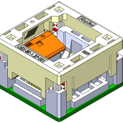
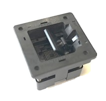
Auto loading machine → Open top
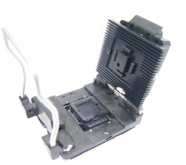
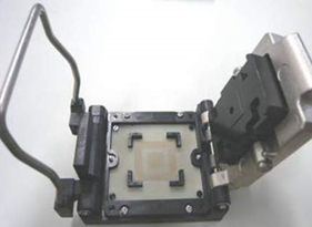
Manual operation → Clam Shell
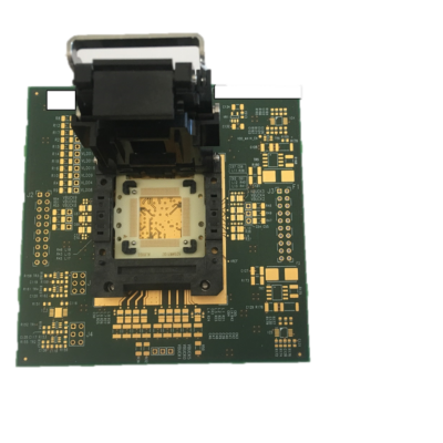
BGA socket
-
Burn-in Sockets
Reliability Assessment /
For Mass Production -
Test Sockets
Property Assessment /
For Mass Production
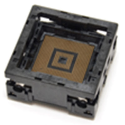
The BGA socket for burn-in is to contact the BGA ball to Pin, and enable electrical connection. There are mainly two types of contact that pinch the side of ball, and sticking probe contact from the bottom of the ball.
We do provide the open top solutions that use latching mechanism to prevent the Package drop from the socket. We can also provide that Heatsink solution for both open top / clam shell sockets for heat dissipation.
Selecting points for BGA socket for burn-in Points
For burn-in sockets, it is important to select based on the usage and environment.
We introduce the key points to determine the specifications of the BGA socket for burn-in usage.
Point#1
Select either open top or clamshell based on method of setting the device.
Point#2
Select the mounting method on the board by either focusing on contact reliability or focusing on maintainability.
Select the solder mounting method if you want to emphasize the contact reliability between the socket and the board, and select the surface mount method if you want to emphasize maintainability.
Solder mounting method / Emphasis on contact reliability
Using 2 points pinch type pin with above 0.65mm pitch. BGA sockets are relatively inexpensive because they are mainly made with molded method.
Surface mount method / Emphasis on maintainability
Using bottom contact probe with vertical movement and more effective for Package warpage. Machined pin options available that enable to support the fine / multi pitch.
Point#3
Consider the method for heat dissipation and high current solutions.
We provide the most applicable heatsink style after running heat simulation. For high current solution, we are able to suggest bypass pin options as necessary.
BGA socket for burn-in Common problems Issues
Since the BGA socket for burn-in require to have stable performance even in a harsh environment, it is necessary to incorporate measures to avoid troubles in advance by utilizing simulation technology. Here are some common problems you may have when using BGA sockets for burn-in and solutions to them.
Issues #1
Thermal runaway due to PKG's self-heating
Devices with high self-heating of PKG may cause thermal runaway during burn-in tests in high temperature environments. If this happens, you will not be able to perform a burn-in test.
Solutions
Utilize thermal analysis simulation and avoid it by installing the optimum heat sink!
Issues #2
The Pad and pin do not make good contact
Even though sockets and devices are elaborately designed, if the PKG warps during the burn-in test, the position of Pads will change, which causes poor contact. If it is the case, Burn-in test will not work, so it is necessary to ensure stable contact regardless of the PKG warpage.
Solutions
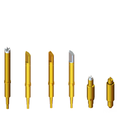
Select the most suitable one from 3 types of contact pin tip shapes!
Issues #3
Repeated burn-in testing reduces yield
For Au-plated contact pins, the base material of the contact pin may be exposed as the burn-in process is repeated. If this happens, the tin plating on the PKG Pad will be peeled off and transferred, and the contact between the socket (contact pin) and the device will become poor. As a result, the burn-in test will be NG and the yield with the device will decrease.
Solutions
Achieves a long life with contact pins that use ES plating!
BGA socket
BGA socket lineup for Burn In Solutions
-
Spring Probe Pin
Enplas's own design will provide internal short circuit of probe pin with low resistance value (Ave 50m ohm or under)
Enplas provides suitable socket design proposal to meet required specification -
Open top BGA two contact socket
Stable contact performance due to (two-point contact) structure
Double door structure makes it easy to insert PKG -
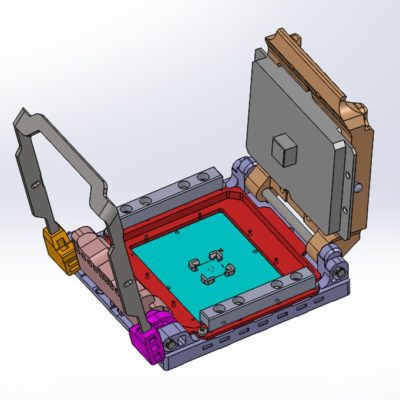
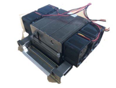
Custom socket for high power liquid cooling system
Not only BGA, and LGA, but also various type of package including QFN can be designed by using a socket that is suitable for the thermal head size
-

LCF series (general-purpose molded frame)
Low price and quick delivery for various devices up to 100mmx100mm
Replacible on site by surface mounting method -
Carrier Socekt
Easy package handling with carrier PCB
Multi-height pusher for different thickness devices -
Sockets for power devices
Compatible with various power devices that are not handled by other companies
It is also possible to consider the optimum pin arrangement and support large currents of power devices. -
Open Top Socket with Cover
Open top socket integrated with a mechanism that protects the entire top surface of the PKG.
Socket with cover to prevent dust in the air from coming into the socket. -
Improved cover handling socket for large devices
Enable to operate with stable pressing force for high pin count solutions.
-
Height adjustable socket
By just switching a lever, the height of Heat sink pressing surface is adjusted to enable one IC socket to test PKGs of different thickness.
-
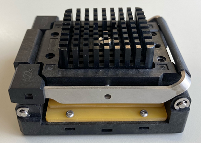
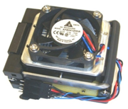
Socket with heat sink
Heat Sink will reduce the increase of device temperature by contacting device surface with this parts and radiating the device heat into the air.
-
Burn-in socket with heat pipe
High heat dissipation performance due to the heat circulation structure of the heat pipe improves the accuracy of individual temperature adjustment tests for high heat generation PKG.
-
Individual Temparature Control System
Heater and temperature sensors can be attached to control the temperature of the device for each socket.
Achieves more accurate temperature control in comparison with general burn-in equipment (temperature setting ± 3 ° C) -
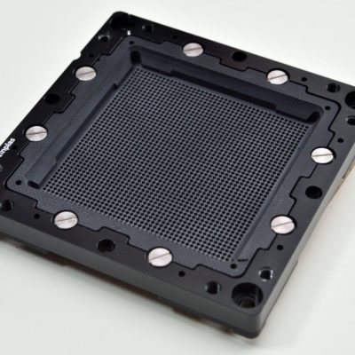
High pin count BGA socket (VC contact)
Stamped contact pin and molded frame realize significant cost reduction for large PKG
Replacible on site by surface mounting method -
ES Plating
By developing special plating (ES plating), the life of burn-in socket contacts has been extended in high temperature environments.
Maintenance costs have also been significantly reduced by reducing re-gold plating costs, etc. -
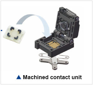
AM contact series
Low price and quick delivery for various devices by using machined Contact unit
Replacible on site by surface mounting method
Our lineup of BGA sockets for burn-in Lineup
MAX Grid MAX PKG O.D Socket External shape
| Socket | Specification | Specification | ~100pin | 500pin | 1,000pin | 2,000pin | 3,000pin | 5,000pin | 7,500pin | 10,000pin |
|---|---|---|---|---|---|---|---|---|---|---|
| Clam Shell | C Socket (XXXL-LCF) | 0.6mm~1.27mm | PK SIZE □100mm#bg# | |||||||
| C Socket (XXL-LCF) | 0.6mm~1.27mm | PKG SIZE □80mm#bg# | ||||||||
| AM Socket (L-LCF etc) | 0.3mm~1.27mm | PKG SIZE □55mm#bg# | ||||||||
| PS Socket | 0.15mm~0.65mm | PKG SIZE □55mm#bg# | ||||||||
| VC Socket | 1.0mm | ~2,601 Pin PKG SIZE □52.5mm#bg# | ||||||||
| 0.8mm | ~1,849 Pin PKG SIZE □35mm#bg# | |||||||||
| Open Top | AM Socket | 0.3mm~1.27mm | PKG SIZE □33mm#bg# | |||||||
| AM / PS Socket | 0.3mm~1.27mm | PKG SIZE □23mm#bg# | ||||||||
| Pinch Contact | 1.0mm | ~1,681Pin PKG □SIZE 42.5mm#bg# | ||||||||
| 0.8mm | ~1,369Pin PKG □SIZE 31mm#bg# | |||||||||
| 0.65mm | ~1,764Pin PKG □SIZE 29mm#bg# | |||||||||
Please feel free to contact us with
your questions regarding burn-in sockets.
Contact Us
- Is it possible to manufacture a socket with more than 10,000 pins?
- Is it possible to support high pins counts of BGA socket?
- How do you prevent the BGA heating with the socket ?
- Can the BGA socket support ultra-fine pitch?
- What kind of analysis can you provide ?
- Is there export to overseas and get local support?
- What should I do if there is a problem?
- What is the guaranteed cycle?
- What temperature can it be used in?
- I would like to consider a burn-in socket, but what information do you need?
- How long does it take to deliver?
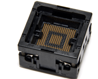
BGA Test sockets have electrical connection with PKG through contact pin and BGA balls. The contact pins used for BGA Test socket are probe pin (stamped probe) manufactured by Enplas’ original method and Capsule pin which gives stable measurement result regardless of high frequency. Because the contact pin holding part (contact unit) is removable, all contact pins are replacible by just replacing the units, or replacing a specific pin. In addition, the unit uses FR4 material, which has a cost advantage, and the target PKG size (pitch, number of pins, pin arrangement, etc.) can be changed by replacing the unit, so it can be used economically. It is possible to have it.
Key points for selecting a BGA Test socket POINTS
For BGA Test socket, it is necessary to select the optimum specifications depending on the usage, environment, and the function of device. Here are important points in determining the specifications of BGA Test socket.
Point1
Select the most suitable probe pin according to the requirements of electrical characteristics
If high frequency characteristics are important, select capsule content pin or coaxial contact pin
Point2
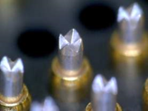
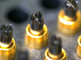
Select the pin tip shape and stroke amount for a stable contact
As for the crown shaped contact pin, the more protrusions the pin tip has, the more advantageous for contact stabiliby. Therefore, 4-point protrusion is applied, which is cost-efficient too. For even more stable contact, select conical 1-point contact. Also, select a pin stroke amount according to the testing machine.
Point3
Select the material of the contact pin tip depending on the required durability
In order to improve durability or to prevent Sn from adhering to the contact pin, there are some options for the contact pin tip, carbon coating, palladium alloy or SK material. These lead to improved life and contact stability
Common problems of BGA Test socket Issues
Since BGA Test sockets need to keep stable performance even in harsh environments, it is necessary to incorporate measures to avoid troubles in advance by utilizing simulation technology. Here are common problems and solutions when using sockets for BGA Test sockets
Issues #1
Requirement for High frequency band
BGA Test sockets are often required to support high speed signal measurements. However, since the characteristics of normal contact pins do not correspond to the high frequency band, it is necessary to adopt contact pins that meet the required specifications.
Solutions
Use Capsule contact pin, which has short total length!
Use Coaxial contact pins, which is impedance-matched!
Issues #2
Requirement for durability
Durability is important because BGA Test socket is used repeatedly. Since the standard contact pin is made of Au plated beryllium copper, the plating on the pin tip is subject to wear out and Sn adhesion when used repeatedly, resulting in poor contact.
Solutions
Avoid pin wear by using palladium plating and SK material!
Avoid Sn adhesion by using carbon coating!
BGA socket
BGA socket lineup for Test Solutions
-
Spring Probe Pin
Enplas's own design will provide internal short circuit of probe pin with low resistance value (Ave 50m ohm or under)
Enplas provides suitable socket design proposal to meet required specification -
Test socket with heat pipe
The high heat dissipation capacity enabled by the heat pipe's thermal circulation structure allows for the measurement of devices with high-heat-emitting packages.
-
Conductivity Carbon Coating
Achieved a significant longer life of contacts by preventing solder migration
Achieved high durability with high slidablity and hardness -
Capsule contact
The short-length probe pin structure (total length 1.5 mm) realizes good high-frequency characteristics.
Ideal for high-speed transmission and low-voltage products -
Coaxial Contact Pin
Coaxial structure is the most suitable solution for high frequency characteristics requirement.
Minimizes crosstalk performance with shielded metal housing. -
ES Plating
By developing special plating (ES plating), the life of burn-in socket contacts has been extended in high temperature environments.
Maintenance costs have also been significantly reduced by reducing re-gold plating costs, etc.
Our lineup of BGA sockets for burn-in Lineup
| Socket | Pitch | Pin length | Operation Temperature | Lifetime | Load | Load |
|---|---|---|---|---|---|---|
| Press Probe | 0.8mm | 3.4mm | -55℃ ~ +120℃ | 200,000回 | 30gf | >20GHz at -1dB / >20GHz at -10dB |
| 4.2mm | -55℃ ~ +120℃ | 200,000回 | 22gf | 17.4GHz at -1dB / 14.5GHz at -10dB | ||
| 0.5mm | 3.45mm | -55℃ ~ +125℃ | 200,000回 | 25gf | >20GHz at -1dB / >20GHz at -10dB | |
| Capsule Pin | 0.8mm | 1.5mm | -55℃ ~ +125℃ | 250,000回 | 25gf | >20GHz at -1dB / >20GHz at -10dB |
| Probe Pin | 0.8mm | 3.3mm | -55℃ ~ +125℃ | 200,000回 | 25gf | >20GHz at -1dB / >20GHz at -10dB |
| 0.5mm | 3.45mm | -55℃ ~ +125℃ | 200,000回 | 25gf | >20GHz at -1dB / >20GHz at -10dB | |
| 0.4mm | 3.75mm | -55℃ ~ +125℃ | 1,000,000回 | 25gf | >20GHz at -1dB / >20GHz at -10dB |
Please feel free to contact us with
your questions regarding test sockets.
Contact Us
- Is it possible to manufacture a socket with more than 10,000 pins?
- Are there sockets for writing program data?
- Is it possible to support high pins counts of BGA socket?
- Is it possible to support high frequencies in the BGA test socket?
- Can the BGA socket support ultra-fine pitch?
- What kind of analysis can you provide ?
- Is there export to overseas and get local support?
- What should I do if there is a problem?
- What is the guaranteed cycle?
- What temperature can it be used in?
- I would like to consider Enplas’s test socket. What kind of information I need to provide ?
- How long does it take to deliver?